Background
Back in January of this year, I picked up a Poco Kit from Natalie the nerd, hoping to be able to convert a damaged Gameboy Color that I got for a song on ebay a while back. In my opinion, the Gameboy Pocket (GBP) is a far superior form factor to the Gameboy Color (GBC). Unfortunately, the GBC’s board is slightly too tall to fit inside a GBP’s case and the buttons don’t line up with the button holes in case, either.
Note: The Gameboy Pocket is generally referred to as the MGB, since that’s the model number that nintendo used. But I’ll refer to it here as GBP for simplicity.
So the “simplest” solution is to slice off the bottom of a GBC, right below the cartridge slot, and do the same to a GBP board. Then perform the necessary wiring between them. There’s a couple of other considerations, since the GBP uses some extra electronics for dealing with button presses.
The bottom half of this damaged GBC I had was in really rough shape, but the top half was in perfect condition, which means that I had the perfect piece of hardware for this project.
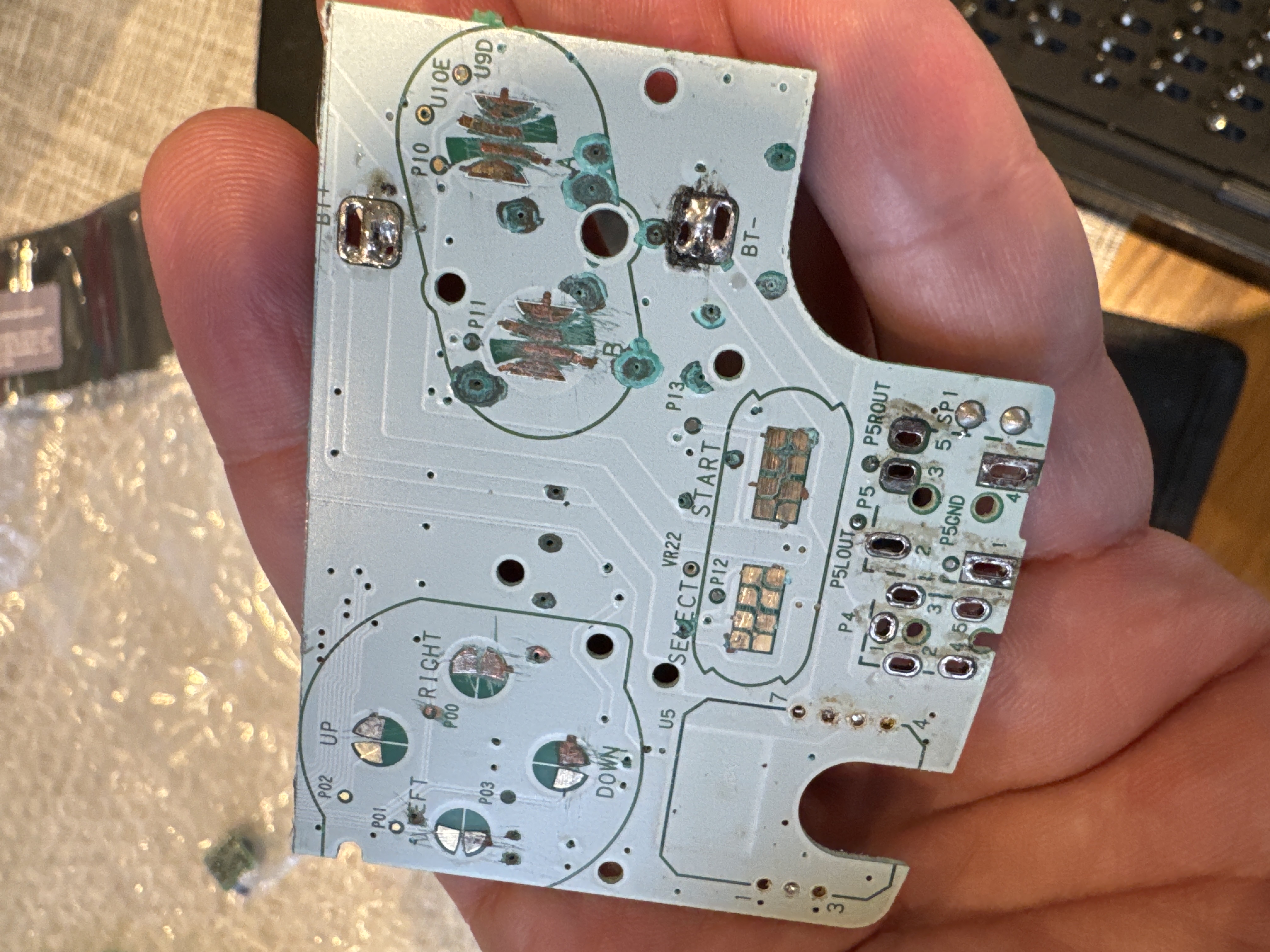
The bottom, damaged half of a Gameboy Color
Natalie’s kit includes 2 parts: a bottom half which needs a few parts from the donor GBC (the power and headphone jacks and a power regulator board) and a ribbon cable which lines up with the top GBC half. By using Natalie’s kit, you only need a donor GBC and not an additional donor GBP.
Unfortunately, I screwed up somewhere and the ribbon cable didn’t align the two parts properly when putting the shell back together. I don’t know what I did wrong, but some of the ribbon cable tore and I decided to give up on that approach.
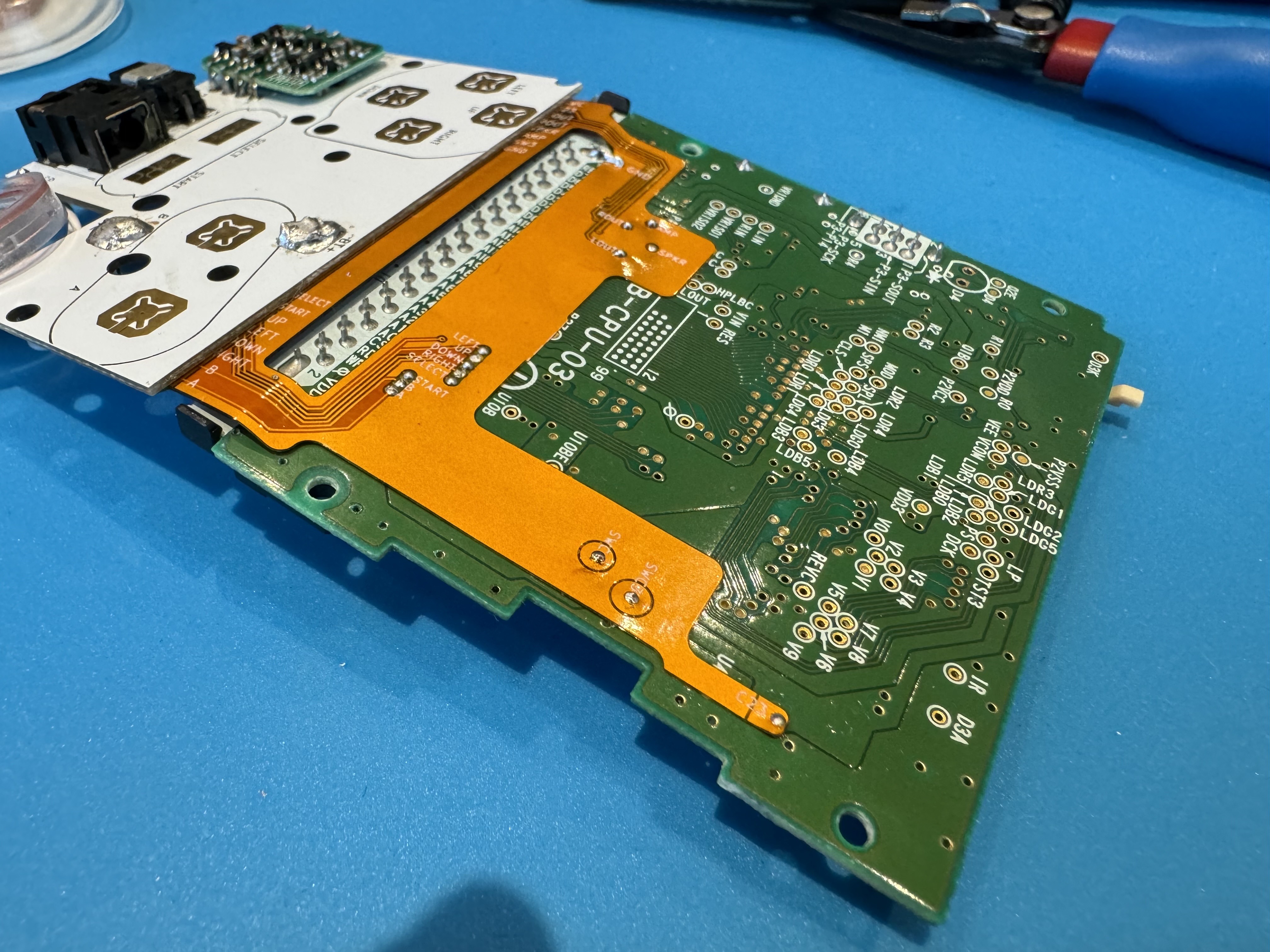
The ribbon kinda folded on itself
Since beginning this project, Natalie released a v2 of the kit, but I had already dropped a pretty significant amount of money on the first version, so I opted to hand-wire this myself and avoid sinking more money into the project.
Insides
I removed the ribon cable and started looking at what I needed to do to complete this project. Basically, I just had to solder in 22 wires in total:
- 2 for the power switch
- 4 for the LCD
- 16 to connect the bottom board to the top board
I cut up some wrapping wire and got started.
My skills are still improving and I’m trying to get better about strategizing how I approach these types of things. Part of this is getting better at routing the wires, but another part is just trying to not be so sloppy. This is as neat as I could manage.
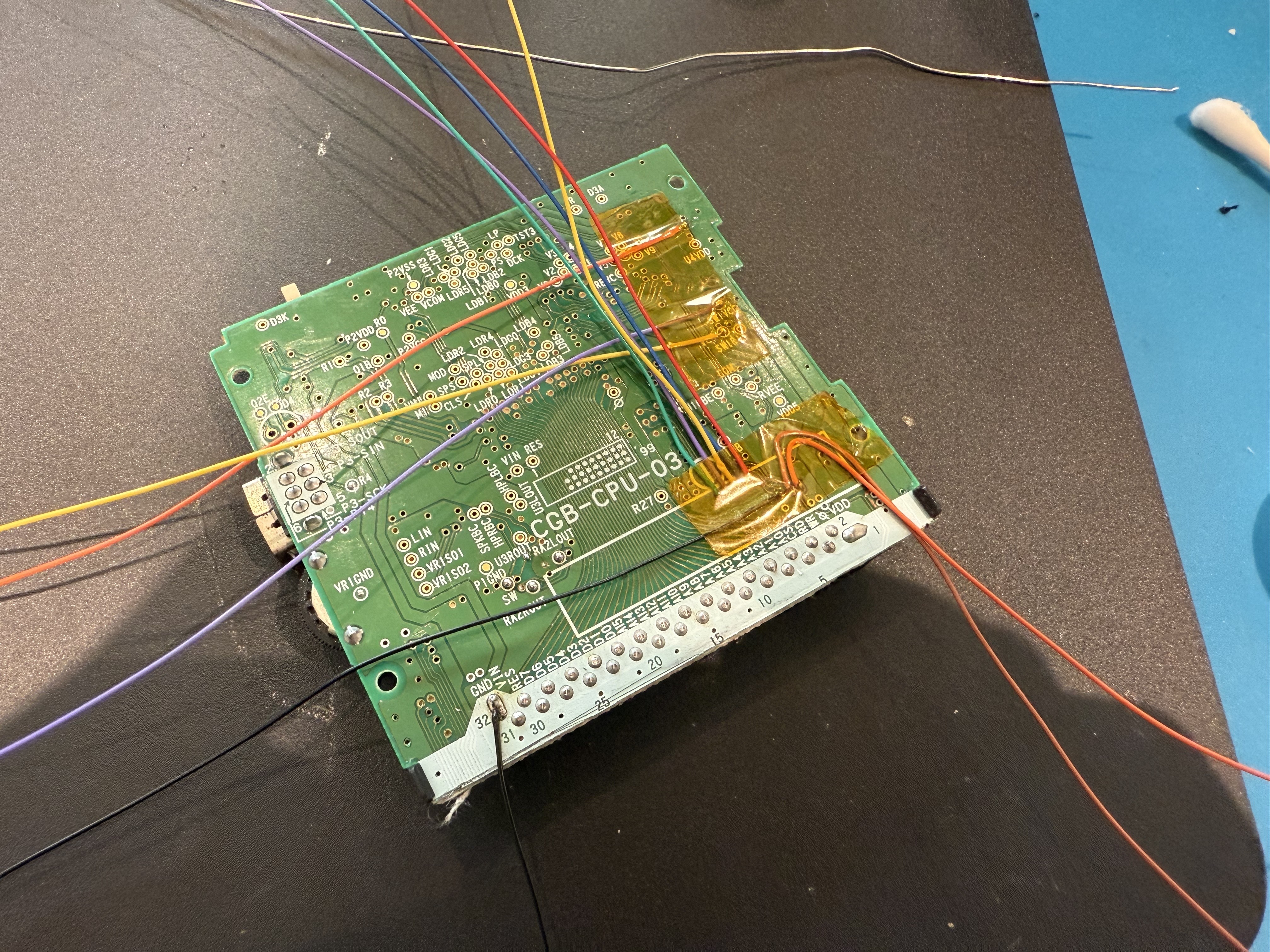
Soldering in the wires for the speaker, buttons and power
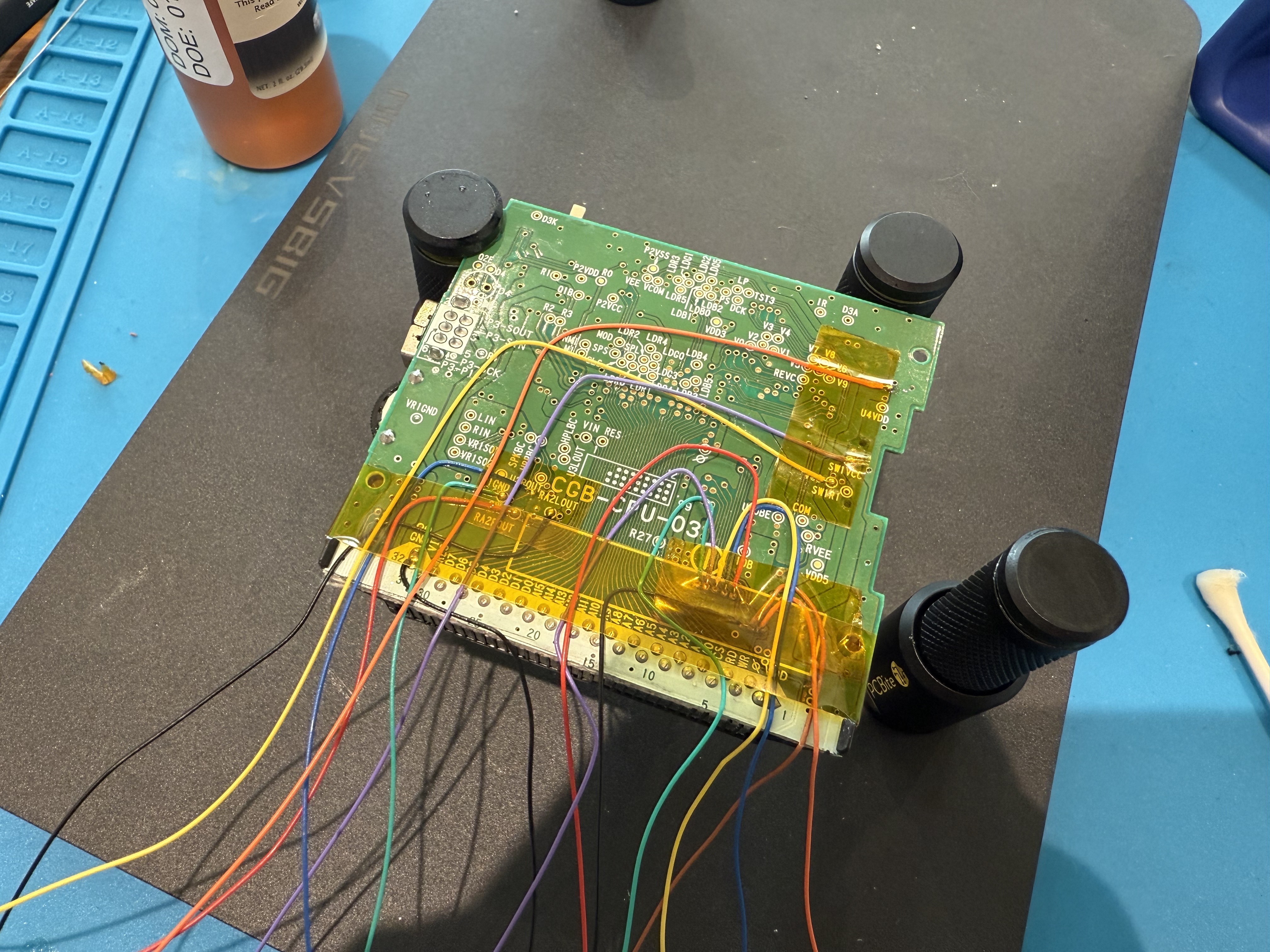
Re-routing the wires as cleanly as I could manage
While doing this I took meticulous notes so I’d be sure to solder the correct wires to the correct pads. I spent a lot of time verifying continuity to ensure I had no bridges.
The end results was this:
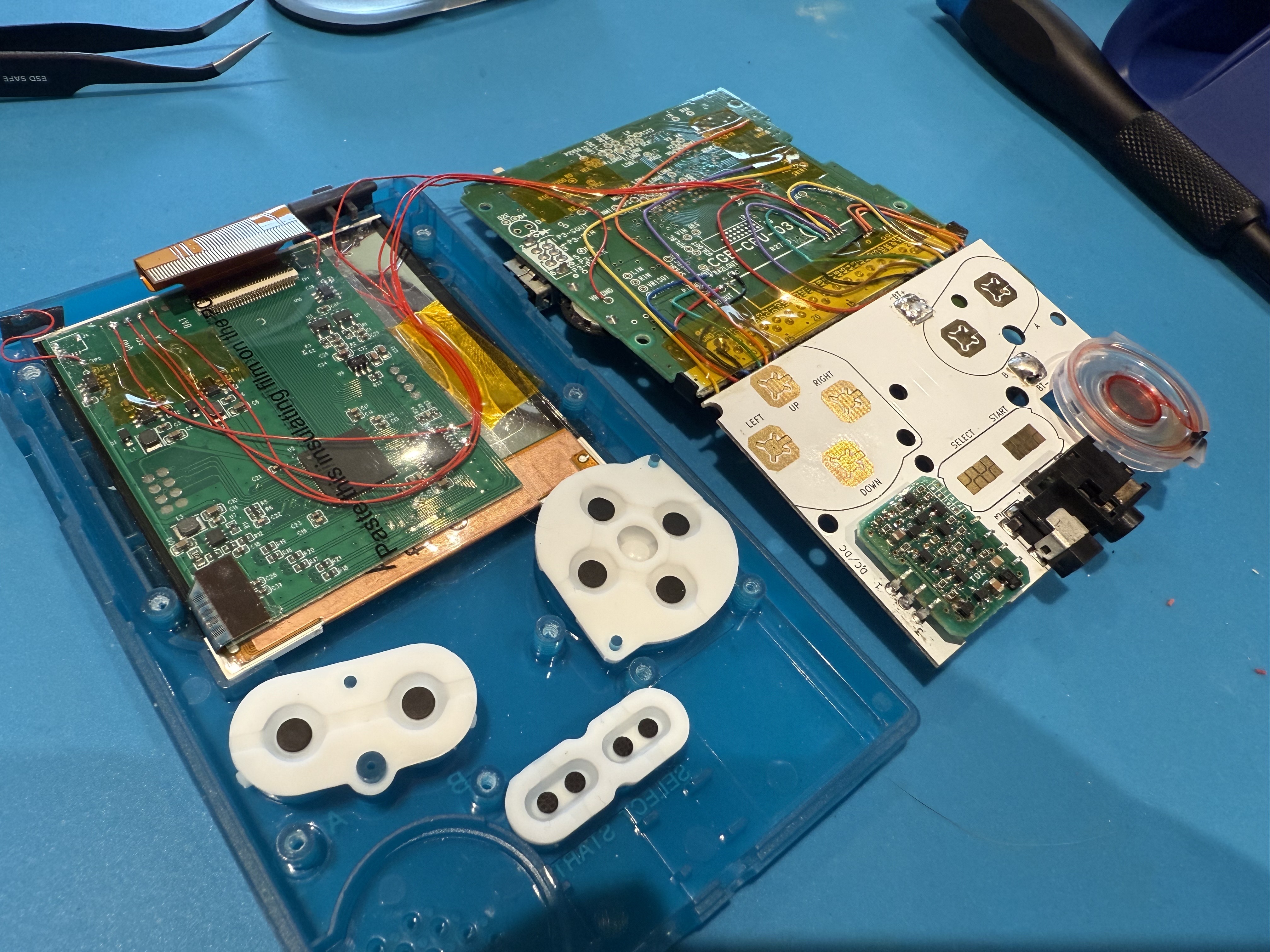
The button-side of the board, where all the wires are visible
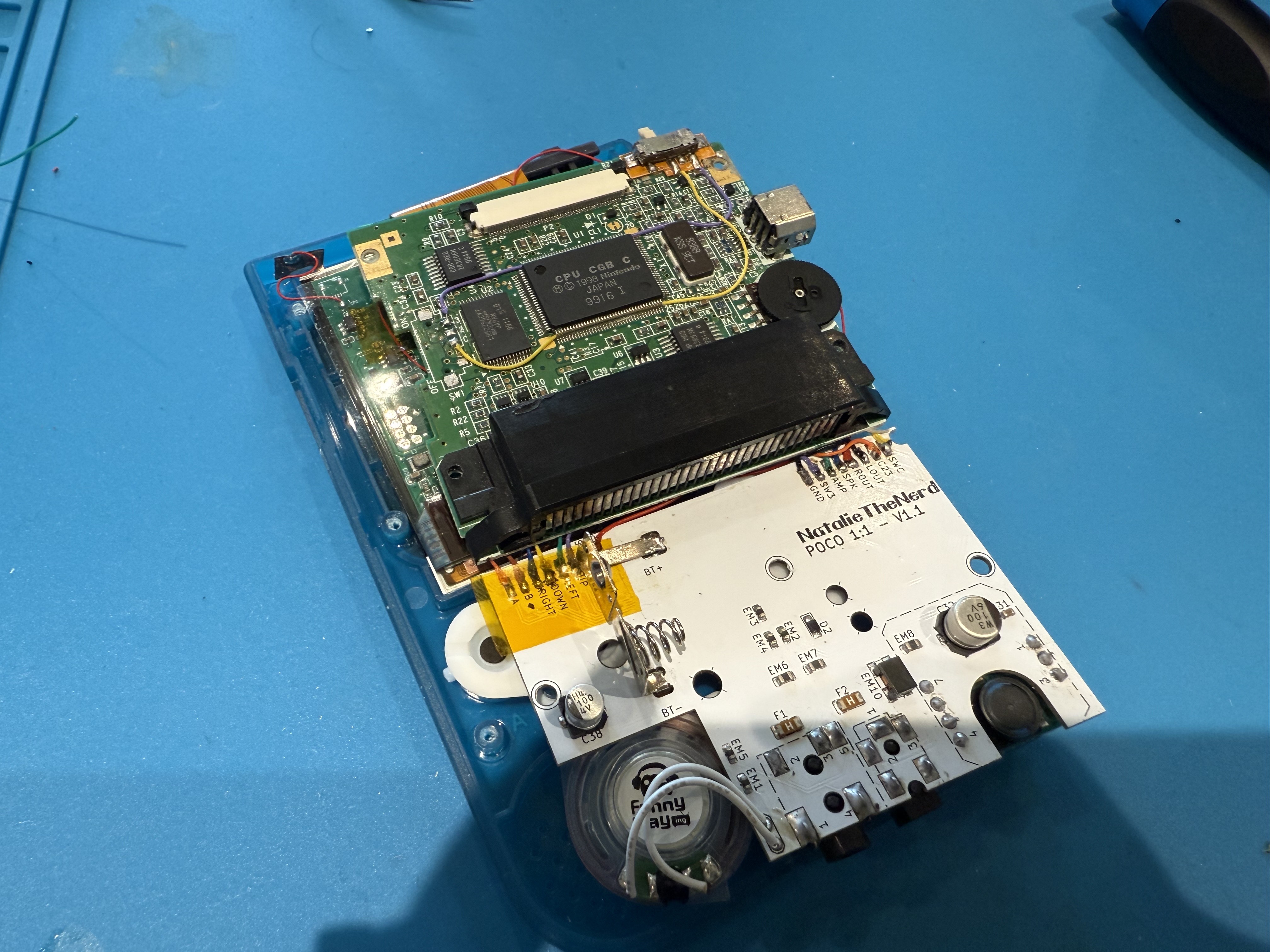
The rear-facing portion. I'm very satisfied with my power button wire routing, here.
Finished project
So this is the finished project:
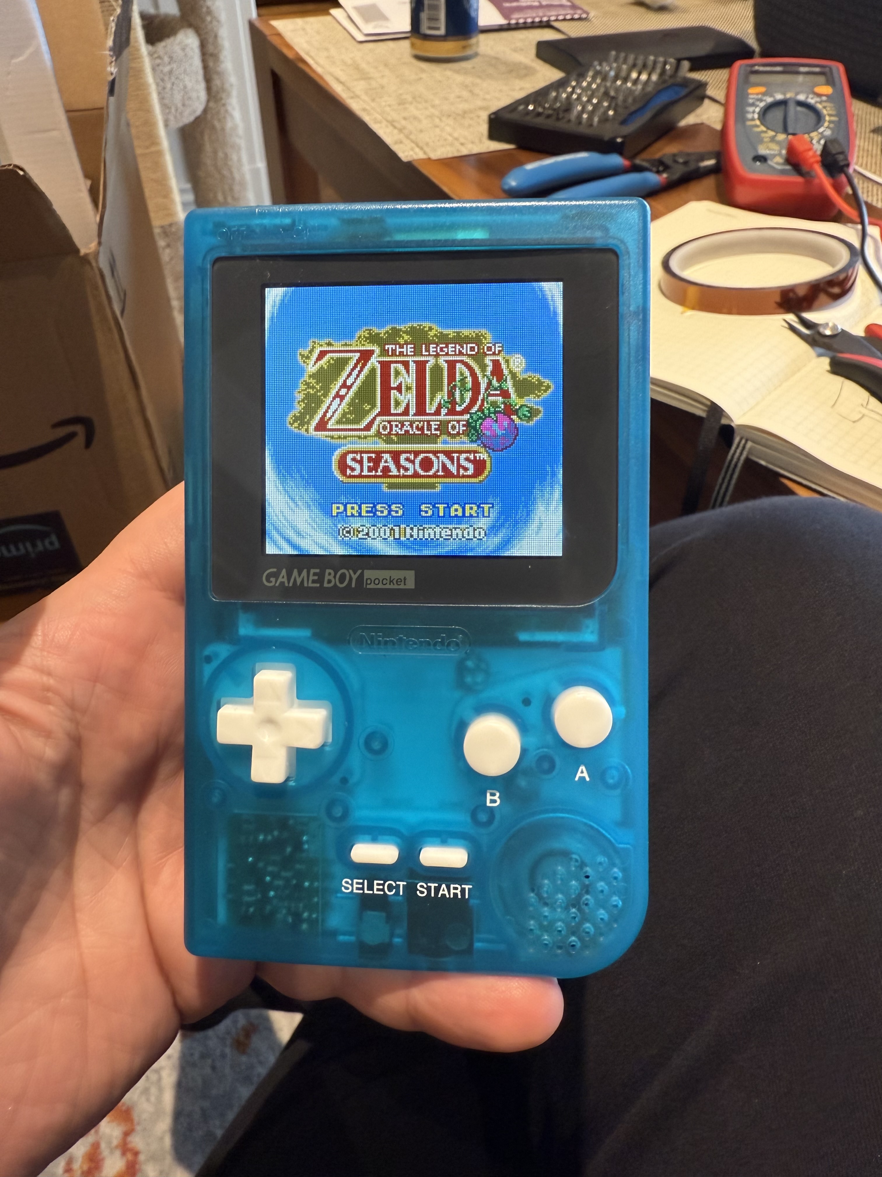
The front of the completed Gameboy Pocket Color
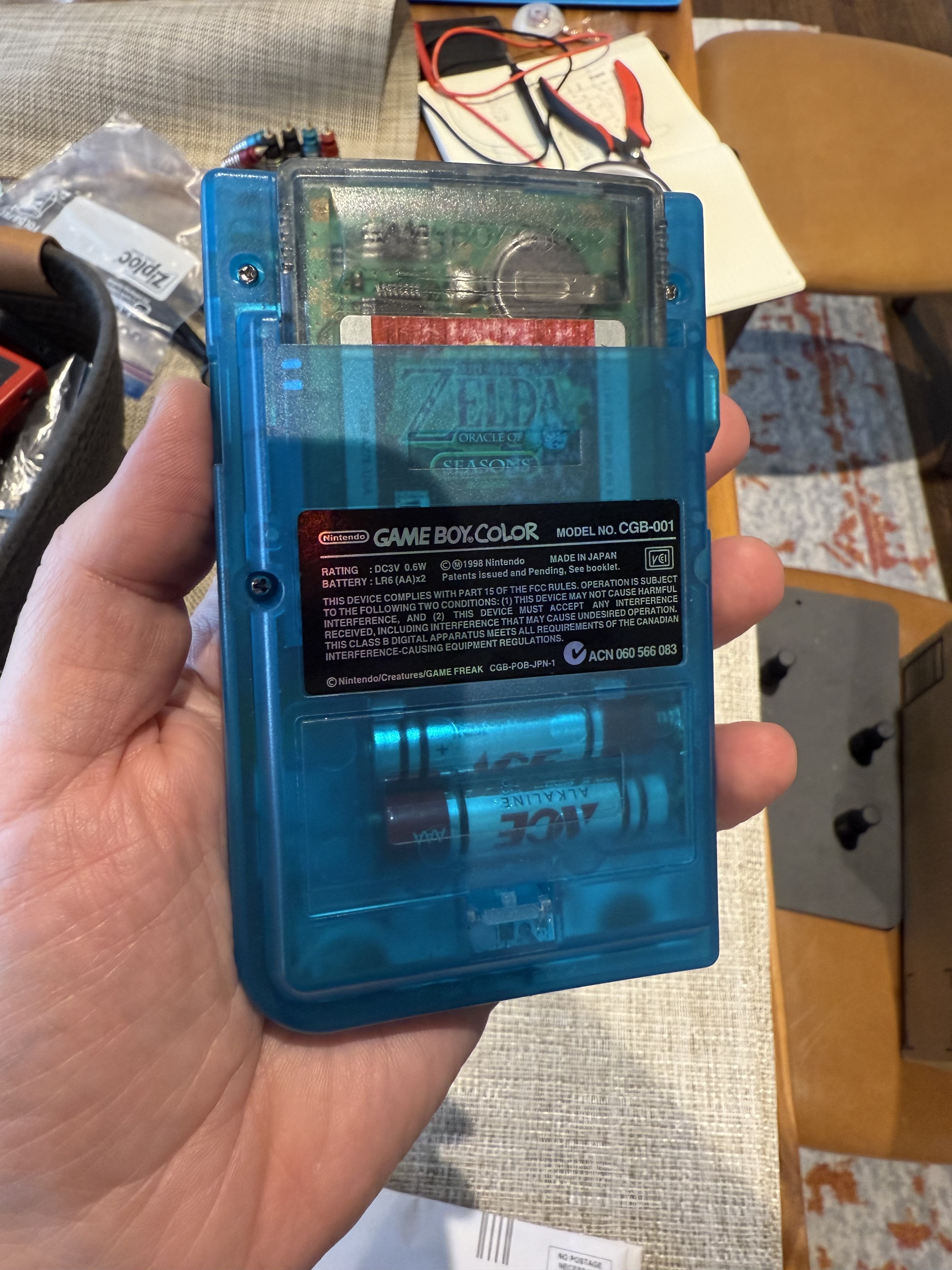
And the back, with a spiffy sticker
Overall, I’m pretty happy with this. It works, but not perfectly.
The power switch is a little sticky. The power switch had to be relocated to the top since the GBP has the switch on top, where the GBC’s IR LEDs live. This requird desoldering the IR LEDs and power switch and using Natalie’s mounting board to mount the switch in its new location. While doing this, the switch was filled with flux and got kinda gross. I did open it up and attempt to clean it, but the switch really never felt the same after that. I actually ruined another switch trying to do this and the switch that wound up in the final product is from another donor GBC that I have.
Additionally, the up and down D-pad buttons aren’t terribly responsive. I’m not sure what’s going on, but I’m going to need to open it up again, and maybe clean it or something, but that’s a task for another day.
The power button is also reversed. The GBP case labels the switch in the off position when it’s switched towards the left edge of the case, but in my case, that’s the ON position. I’m not sure if that’s expected or not, but it caught me off-guard.
Final thoughts
If I were to take this project on again, I’d plan even better for the how the wires are routed, for sure. I’d really like to be able to get some super-clean wire routing done where no wires have to cross over and potentially get crushed.
I’d also opt to use a different type of wire. The wire I used is pretty thin, solid-core wrapping wire, but it’s delicate and can break if bent too many times. That makes it a really poor fit for this type of project. I need to invest in some better wire. Like, the wire that came with the LCD is a lot more flexible AND it’s thinner. I’d definitely go that route for some of this if I were to do it again.
I also really need to practice removing power switches and cleaning them. For next time.
Overall, though, I am happy with this project and I’m super happy with the case I chose for it. It’s really attractive.
